Undoubtedly, the welding process can be called one of the common points of material engineering and mechanics. Researchers in the field of mechanics examine welding from the point of view of strength under loading and force tolerance, while from the point of view of material science researchers, the issues of heat transfer, the occurrence of microcracks caused by cooling, and the metallurgical properties of the part after welding are important.
Undoubtedly, the welding process can be called one of the common points of material engineering and mechanics. Researchers in the field of mechanics examine welding from the point of view of strength under loading and force tolerance, while from the point of view of material science researchers, the issues of heat transfer, the occurrence of microcracks caused by cooling, and the metallurgical properties of the part after welding are important.
T joint weld modeling and analysis problem statement in Abaqus
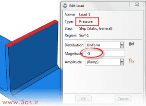
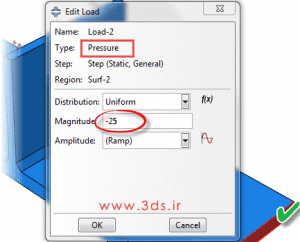
Consider two steel pieces with known mechanical properties that are welded together. We intend to subject the structure to mechanical loading and analyze its behavior in Abaqus software. Obtain the stress contour of the structure under this load.
Solving T-shaped weld modeling and analysis problem in Abaqus
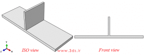
According to the above figure and the three-dimensional nature of the problem, create the desired drawing for the cross-section of the part. For this purpose, consider a three-dimensional and deformable model from the Part environment. Using the set of points (0,0), (450,0), (450,16), (230,16), (230,141), (220,141), (220,16) and (0,16) the related drawing Create the cross section and extend the piece along the Z axis by 150 units (dimensions are in mm).
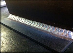
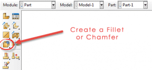
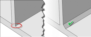
The type of connection in this issue is a fillet weld type, so using the tool specified in the figure below, in the Part environment, chamfer the joint of the two pieces on both sides to the size of 7.07 units to create a weld leg.
Go to the Property module and enter the common elastic and density properties for steel (Young’s modulus 200GPa, Poisson’s ratio 0.3 and density 7800Kg/m^3). Then create a homogenous Solid cross-section for the object and assign it to it.
Continue modeling the two welded parts by assembling them in the Assembly environment and enter the Step module to define the solver type. In the series of educational materials of Abaqus software, we talked with you about static and dynamic loads (learning how to apply loads to pieces in Abaqus). The loading on this issue is static and gradual, so create a Static, General solution and accept the existing defaults.
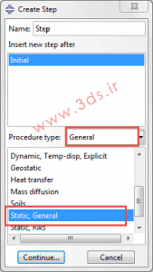
The loading on this issue is static and gradual, so create a Static, General solution and accept the existing defaults.
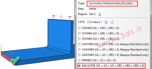
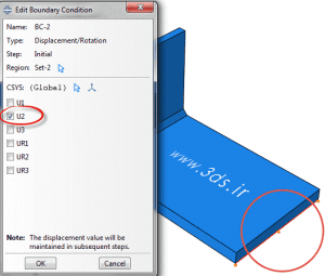
Then bind the left and right edge of the bottom sheet in all directions and the right edge in the Y direction.
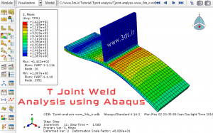
Creating a finite element mesh with the appropriate grain size in the Mesh module will be the last step before submitting the problem for solution. The image below shows the stress contour of the structure due to the aforementioned loading.