This reactor is used in the design of reactions where the conversion rate of one of the reactants is important. In other words, the design of this reactor is done without considering other details, only considering the conversion percentage of one of the reactants.
The design steps of this reactor will be explained in the following example.
1- Design steps
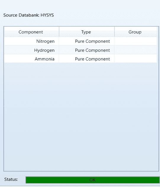
1- Formation of component list
After creating a new case, click on the component list and add the following items.
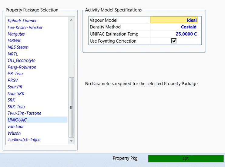
2- Choosing the right thermodynamic equation
Here, our appropriate state equation is uniquac.
3- Definition of reaction
To define the reaction, first click on the Reaction tab and after clicking the Add option, we click the Add reaction option to provide us with the following choices.
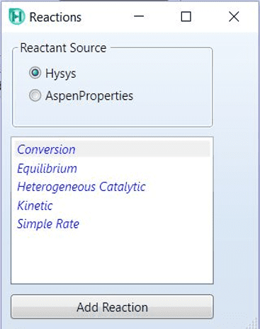
Next, click on the conversion option and in the next step, then click on Add reaction, on Rxn-1 which has just been formed; Double-click to open the reaction information entry window.
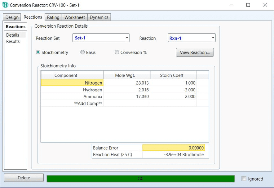
In the stoichiometry info section, we must add all the substances participating in the reaction, both products and reactants, and enter the correct stoichiometric coefficient so that the balance error is equal to zero.
The next step is to determine the base component, which is N2 here.
Rxn Phase specifies the reaction phase, here we can put both overall and vaporphase.
But our most important task is to place c0 or other coefficients (if any), in this part, we place the same number 30 that the problem declared as the percentage of conversion.
The figure below is a summary of what we did.

Definition of reaction 2
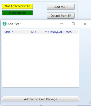
But in the above figure, as you can see, our reaction calculations are not yet connected to our thermodynamic equation or fluid package. Therefore, by clicking on the Add to FP option, we finish our half-finished work.
Because it is possible that you may use several FPs in complex simulations; When you hit the Add to FP option, the software will tell you which set of FP to connect you to, and since we don’t have one more set, we’ll accept that one.
The figure below shows our claim.
4- We enter the simulation environment, for this we click on simulation on the left and bottom of the screen.
5- Select the conversion reactor from the palette and add it to the simulation environment. We complete the connection tab as shown below.
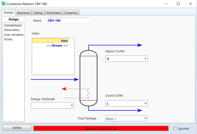
design
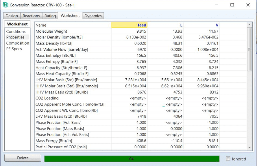
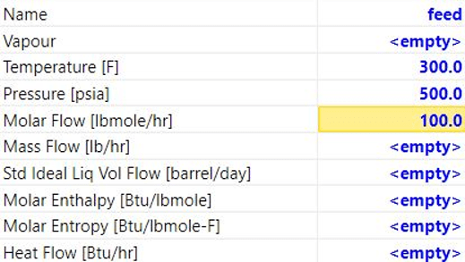
6- From the woksheet tab, we enter the feed information.
Definition of reaction 5
Of course, we complete the flow information from the composition part, which here are 30 to 70.
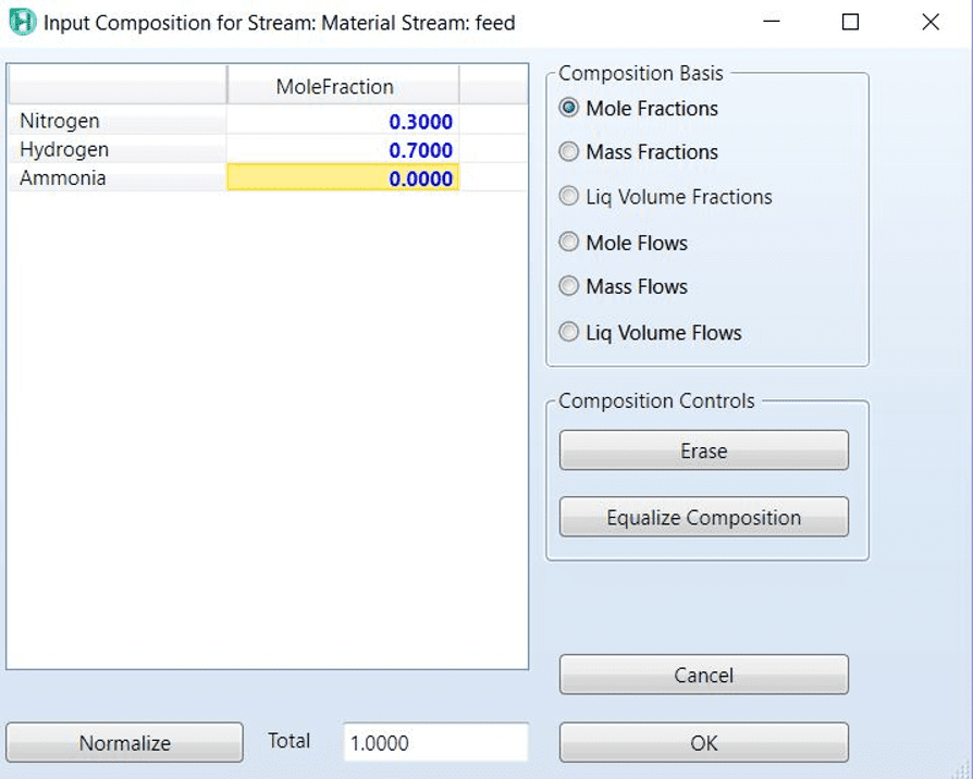
Definition of reaction 6
7- We add the reaction from the reaction tab and the reaction set section.
The reactor is run and the simulation is completed.
Chemical reaction 7
In this section, you can view the output information by referring to the worksheet.