Studying and simulating processes and laboratory tests is one of the most obvious and widely used aspects of using Abaqus software. Examining the results of tensile, impact, or three-point bending tests in this software, along with the practical results, are abundantly noted by researchers in authentic scientific and research articles. Since a wide range of engineering studies and experiments are focused on metallic materials with plastic behavior, we decided to investigate the behavior of the structure in the plastic region through a process similar to three-point bending analysis in Abaqus. Stay with us…
Three-point bending analysis problem statement in ABAQUS: Plastic deformation in ABAQUS
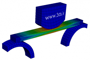
Consider a 200mm long cube with a square cross section of 10mm side length. The cube is placed on two crescent-shaped supports and a pressure load is imposed on it by a moving object. Examine the behavior of the cubic body in this process.
Field of application: mechanical engineering – civil engineering – materials engineering
More information at: www.simuleon.com
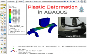
Solving Three Point Bending Analysis Problem in ABAQUS: Plastic Deformation in ABAQUS
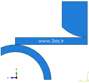
Reducing computational costs in a finite element analysis is one of the main pillars of problem solving, and considering this issue shows the high accuracy and deep vision of the analyst. If you take a quick look at the above picture and review the laboratory process in your mind, you will notice the symmetry of the structure. Therefore, to perform this simulation in Abaqus software, it is enough to model half of it. On the other hand, according to the geometry shown in the image above, we need three separate parts in the analysis: Support, cube and compressive load application section. To speed up the modeling process and avoid giving basic explanations, we have put the geometric model created in Solidworks software for you, so that you can learn how to import models from design software such as SolidWorks to Abaqus. Therefore, we ask you to download the existing step file and call it in the Abaqus software environment from File → Import → Part in the main menu. With the problem geometry ready, go to the Property module and define two different materials. According to the figure below, consider the first material as steel with purely elastic behavior and the second material as steel with elastic-plastic behavior.
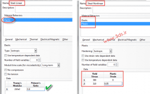
Then, create homogenous Solid sections with each of the above two materials and then assign the section with elastic-plastic behavior to the cube and the section with purely elastic behavior to the support and load application section. Enter all three existing pieces into the Assembly environment. Since the modeling work of parts in Solidworks is done accurately and in the correct coordinates, there is no need to move or rotate the parts, but if you come across a messy model, assemble and place the parts as shown below.
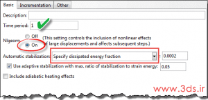
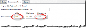
In the Step environment, define a Static, General solver according to the following figures.
According to the modeling of contact processes in Abaqus software, enter the Interaction module and create Surface to Surface contacts according to the example below.
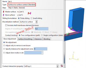
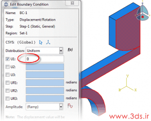
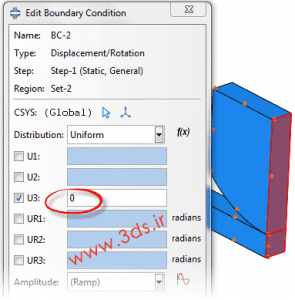
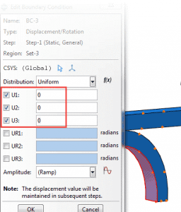
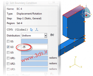
Repeat the same work on the lower level of the cube (and support) and finish the work in this environment. Applying boundary conditions and loading is one of the most important parts of solving finite elements in this problem. Use the following image guide as a model and proceed step by step according to it.
In the last step, create elements of size 2 and 3 units and of Hex type respectively on the cube and other parts (support and load application section) and send the problem to the Job module to solve. The animation below shows the stress contour in this analysis.
Resources
http://engpedia.ir/
http://www.3d.ir/